![Simulation results from COMSOL Multiphysics [1].](/.img/animated_true&extract_300_0_871_490/dam/hightechsystems/public/showcases/Boosting-the-actuator-efficiency-of-reluctance-actuators-with-permanent-magnets/Simulation-results-from-COMSOL-Multiphysics.jpg)
Electromagnetic actuators are an important actuation tool to achieve positioning precision on the nanometer scale. In this realm Lorentz actuators are the mostly used, due to their linear dependence between actuation force and applied current.
The ever growing demand to increase the force efficiency of the actuator leads towards more detailed investigations of reluctance actuation. Overall, we find that a Lorentz actuator is limited by dissipation, while a reluctance actuator is limited by magnetic saturation.
Design topologies
Design studies were executed to find reluctance actuator topologies with reduced magnetic saturation. In order to suppress the magnetic saturation effect of a reluctance actuator, a permanent magnet is placed in parallel to the flux path which leads to an increase of the force efficiency.
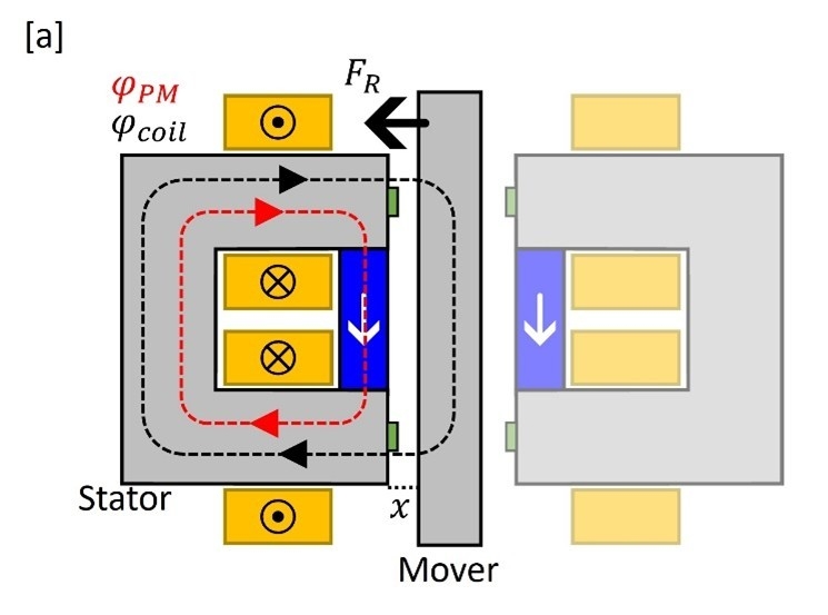
This is schematically depicted in figure 1. The c-shaped stator and the rectangular mover are shown in grey and are made from carbon steel. Two coils are wound around the legs of the c-shaped stator and are connected in series. Applying a current to the coils generates a magnetic flux φcoil (black dashed arrows) to run through the stator and mover.
In figure 1a this current is negative and the flux runs clockwise, while in figure 1b a positive current is applied and the flux runs counterclockwise. In both cases, however, this field pulls the mover towards the stator, due to the quadratic nature of the reluctance force. In order to create a bi-directional actuator two c-shaped stators are needed in the actuator as indicated in figure 1.
The permanent magnet is illustrated in blue, which generates a flux path φPM as indicated by the red dashed line. This flux path stays within the c-shaped stator and – at a first glance – does not contribute to the reluctance force. We find in figure 1a that the flux paths are parallel, which leads to an earlier onset of the magnetic saturation. In figure 1b, however, the flux of the permanent magnet is anti-parallel to the flux generated by the coils and suppresses the effect of magnetic saturation.
simulation results.
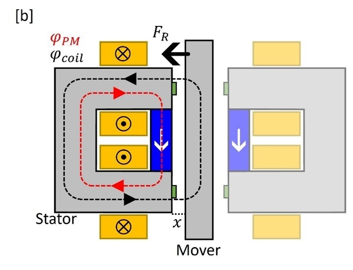
In collaboration with Demcon multiphysics, we used finite element simulations to investigate the actuator efficiency and make quick design iterations. The simulation results using COMSOL Multiphysics software [1] are shown in Figure 2, with the magnetic field strength indicated by the color bar and the direction with the black arrows. A negative current is applied in Figure 2a of -2000 [At]. We find that an average magnetic field of 2.0 [T] is reached in stator, which shows that the carbon steel is saturated.
In Figure 2c the same positive current is applied of 2000 [At], and we find here a lower average magnetic field inside the stator. This indicates that indeed the magnetic saturation is suppressed inside the stator due to the added permanent magnet. In Figure 2b no current is applied. Here, the flux only flows through the stator and no force is applied on the mover.
![Simulation results from COMSOL Multiphysics [1].](/.img/animated_true&w_2400&f_jpeg&q_100/dam/hightechsystems/public/showcases/Boosting-the-actuator-efficiency-of-reluctance-actuators-with-permanent-magnets/Simulation-results-from-COMSOL-Multiphysics.jpg)
force characteristics.
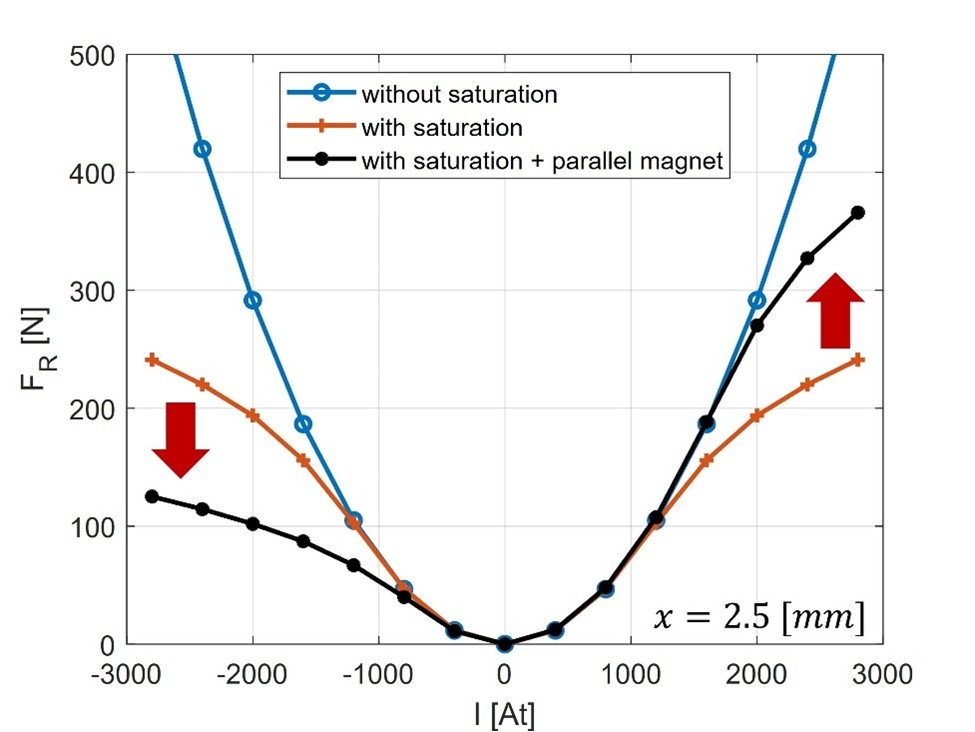
The force output as a function of current is shown in Figure 3. In blue the quadratic behavior for a reluctance actuator without saturation is shown and in orange with saturation effect. The results for an additional permanent magnet are depicted in black and becomes asymmetric. For a negative current magnetic saturation sets in earlier, which results in a lowering of the output force. For a positive current, however, a force efficiency increase of 45% is reached.
conclusion.
Since the reluctance actuator can only pull regardless of the current direction, the actuator design with a permanent magnet implements a preferred directionality of the current, which is a positive current for the design shown here. To conclude, we can increase the actuator efficiency successfully by adding a permanent magnet to the design.