introduction
Our starting point was clear. We already had experience with high-dynamic test equipment based on linear motors. That approach had proven effective at lower acceleration levels, but preliminary calculations showed that it would not take us far enough this time.
The reason is practical: if a linear motor has to deliver more torque, its mass also increases, and that additional mass immediately works against the acceleration you are trying to achieve. At a certain point, the concept no longer scales in a useful way. That is why we moved from a linear principle to a rotational one.
the new concept.
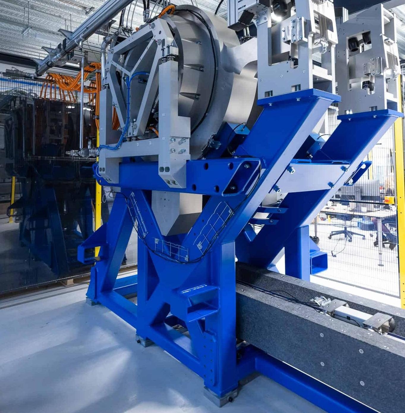
The new concept uses a rotating crank combined with a drive rod to generate a linear back-and-forth motion of the payload. On paper, that sounds elegant. By increasing the arm length, higher tip accelerations can be achieved. But turning that principle into a real machine required much more than selecting a crank and a motor. The design process quickly became an iterative engineering exercise in balancing force, speed, mass and accuracy. We started from the known payload force and desired speed, which together define the mechanical power requirement. From there, we selected motors and used their properties to determine the crank geometry. A short crank limits acceleration. A long crank demands more torque than the motor can supply. The same trade-off appeared in the drive rod: shorter rods create higher parasitic forces, while longer rods add unwanted mass. In the end, the solution only emerged through repeated iterations between all these parameters.