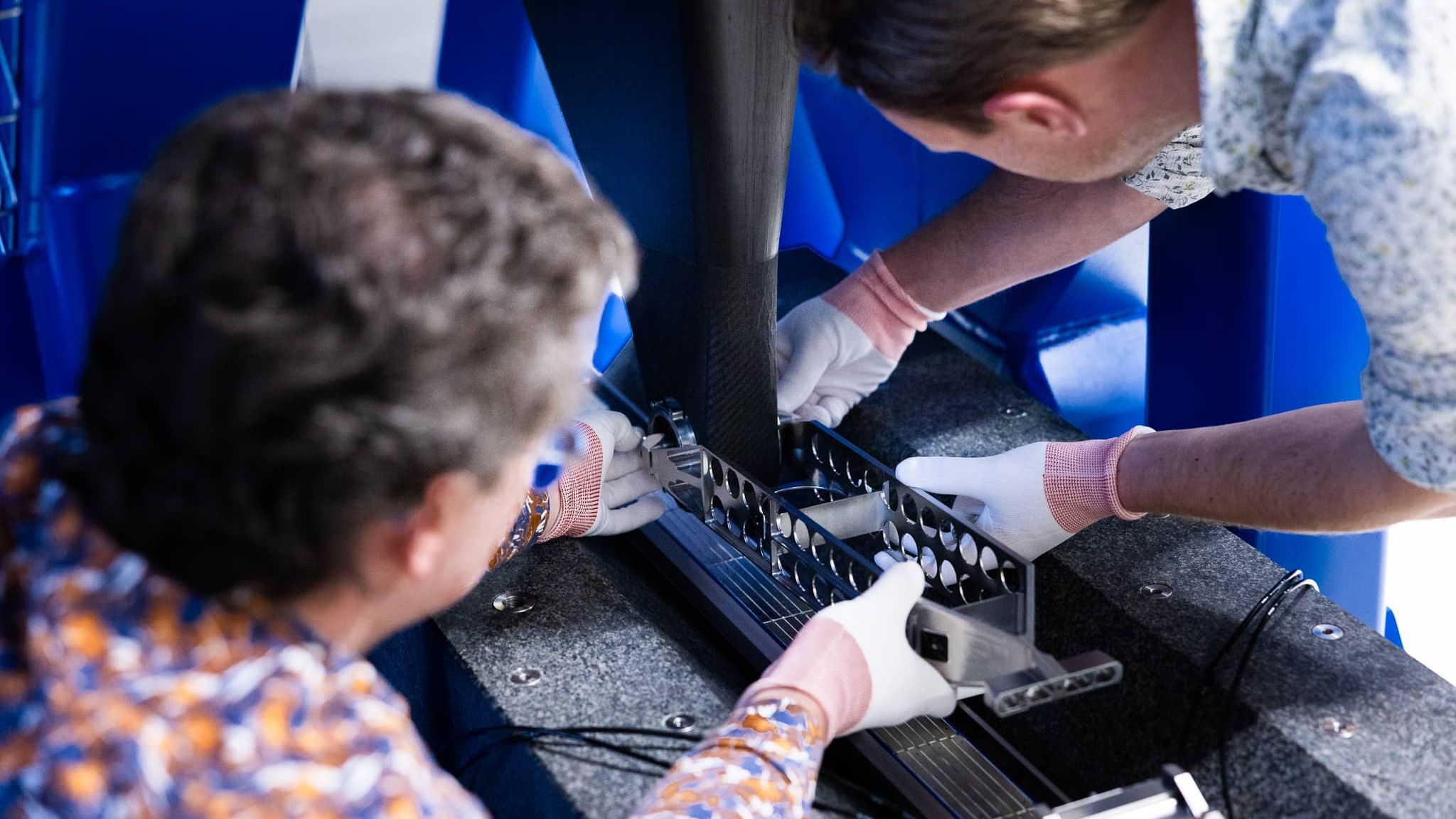
When customers want to increase productivity, higher acceleration often becomes part of the discussion. In theory, that sounds straightforward. In practice, it raises a more difficult question: what happens to components, constructions and interfaces when the dynamics increase far beyond current operating conditions? That was exactly the challenge behind our high-G motion project. The goal was not simply to build a faster machine, but to create a platform capable of testing customer components under extremely high accelerations in a controlled, accurate and repeatable way.
Our starting point was clear. We already had experience with high-dynamic test equipment based on linear motors. That approach had proven effective at lower acceleration levels, but preliminary calculations showed that it would not take us far enough this time.
The reason is practical: if a linear motor has to deliver more torque, its mass also increases, and that additional mass immediately works against the acceleration you are trying to achieve. At a certain point, the concept no longer scales in a useful way. That is why we moved from a linear principle to a rotational one.
the new concept.
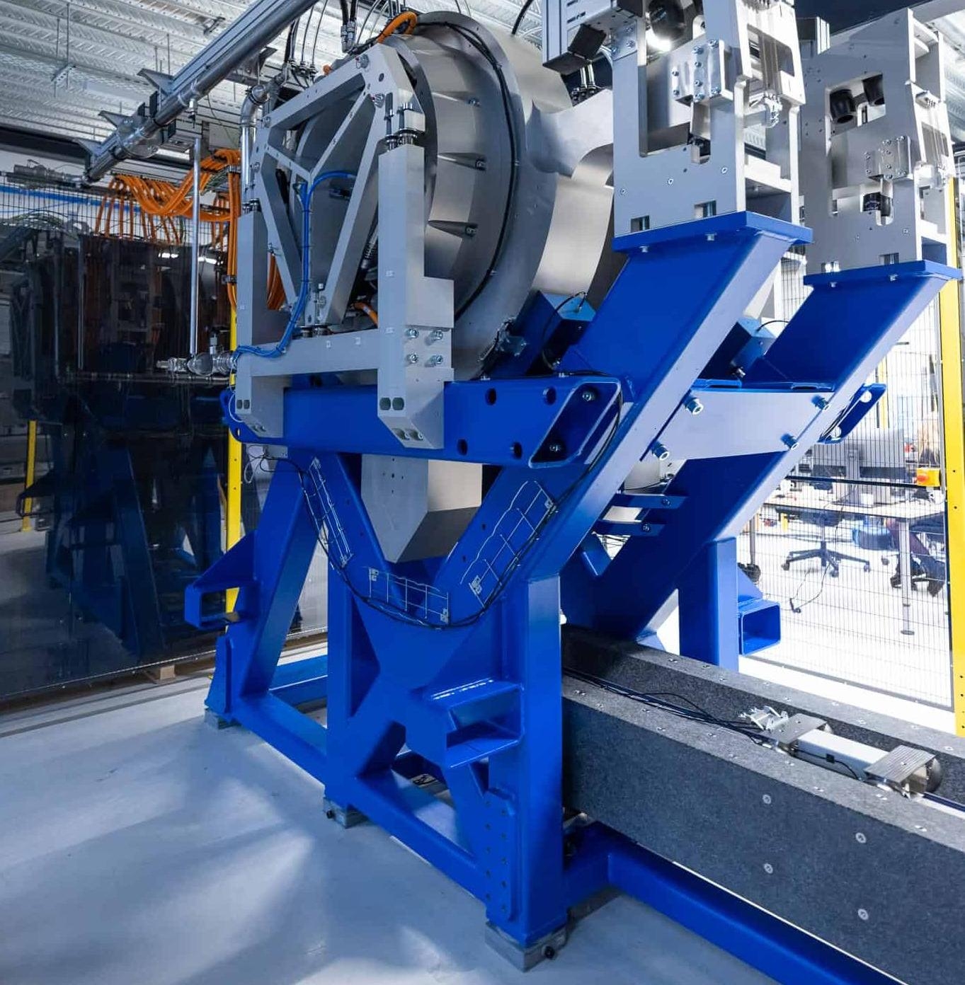
The new concept uses a rotating crank combined with a drive rod to generate a linear back-and-forth motion of the payload. On paper, that sounds elegant. By increasing the arm length, higher tip accelerations can be achieved. But turning that principle into a real machine required much more than selecting a crank and a motor. The design process quickly became an iterative engineering exercise in balancing force, speed, mass and accuracy. We started from the known payload force and desired speed, which together define the mechanical power requirement. From there, we selected motors and used their properties to determine the crank geometry. A short crank limits acceleration. A long crank demands more torque than the motor can supply. The same trade-off appeared in the drive rod: shorter rods create higher parasitic forces, while longer rods add unwanted mass. In the end, the solution only emerged through repeated iterations between all these parameters.
the challenges.
Once the mechanical concept had been defined, the next challenge was electrical power. A machine that produces very high accelerations also requires very high peak power. The selected motors and drives determined the current demand and the necessary DC bus voltage. Because the motion is cyclic, the system sees strong peaks during acceleration and strong dips during deceleration. To reduce the load on the building infrastructure, we added a capacitor bank between the motor drives and the power supply. This makes it possible to absorb those fluctuations more effectively. Even so, the peak power levels are substantial, reaching the megawatt range. That has consequences not only for the drive system, but also for cabinet size, cooling and overall machine integration.
A second major challenge was force reaction in the frame. In a rotating crank system, the center of rotation and the center of gravity do not align. As a result, large reaction forces are introduced into the structure. Those forces reduce accuracy and can also be transmitted into the floor. For a machine like this, that is unacceptable. Our solution was to introduce rotating balance masses on the same axis as the crank.
By designing those masses to generate opposing force contributions, we were able to cancel a large part of the frame excitation. In practical terms, that means better accuracy, less structural loading and far less disturbance to the surrounding environment.
Motion alone, however, is not enough. The system also has to move accurately. Because the setup uses multiple motors, multiple encoders and separate torque demands, a standard control solution was not sufficient. We therefore developed a custom control loop in Simulink. That gave us the flexibility to combine encoder feedback, filters and feed-forward control into a solution that could meet the required positioning performance. An important advantage was that we could simulate the system before ordering the first hardware components. That reduced integration risk and helped us speed up commissioning significantly.
Finally, the machine needed to remain useful beyond the first test cases. That's why we developed a custom TCP/IP interface that allows flexible profile input from the customer. Setpoints are checked against predefined rules, buffered, executed and logged together with sensor data. This enables long-duration and 24/7 operation while keeping the system open for future test scenarios.
conclusion.
What this project shows is that exceeding acceleration boundaries is not about one breakthrough component. It is about combining mechanical design, energy management, force cancellation and control engineering into one balanced system. That is exactly what this high-G motion machine was built to do. And today, it is no longer just a concept on paper. It is in active use as a practical test platform for components under extreme dynamic conditions.