In ground-based astronomy, telescope images are corrected for atmospheric disturbances by using adaptive optics. This is done using a 'laser guide star', an artificial reference that is created by projecting a laser beam into the mesosphere at 90 km altitude. TNO and Demcon have designed a Laser Projection System for this purpose, and are now in the process of building and testing nine of these systems for the Very Large Telescope and the Extremely Large Telescope, both located in Chile. This article focuses on the integration, alignment and testing of this complex and sensitive optomechanical system.
Introduction
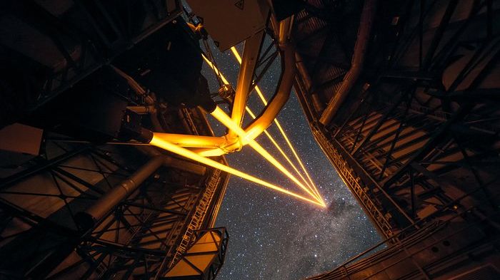
In ground-based astronomy, modern observatories use adaptive optics systems to correct their telescope image for the blurring effects (known as 'seeing') of the Earth's atmosphere. These systems require a distant point source of light (guide star) as a reference in order to continuously characterise the atmospheric distortion effects. In the very narrow field of view that astronomers are interested in, there are often no stars bright enough to be used as this reference. Scientists have therefore developed the concept of a 'laser guide star, an artificial reference that is created by projecting a fine-tuned laser beam from the ground into the mesosphere at 90 km altitude. There, the laser light excites atoms in the naturally occurring sodium-enriched layer, causing them to glow and create an artificial guide star.
In 2021, TNO and Demcon began to work together to design a Laser Projection System (LPS) for this purpose, as well as to build and test nine of these systems.
The first three units will be installed on the ESO Very Large Telescope (VLT) for the Gravity+ upgrade [1].
The remaining six will be used on ESO's Extremely Large Telescope (ELT), which is currently being constructed at the summit of Mt. Cerro Armazones in Chile. When in operation, the LPS systems will enable ELT to create the sharpest ever views of the universe.
After the completion of an extensive design and review phase, the manufacturing, assembly, integration and testing (MAIT) phase of the system began in mid-2023. At the time of writing, the full performance verification test campaign for the first LPS had just been completed. In this article, we will focus on the integration, alignment and testing of this complex and sensitive optomechanical system, with an expected lifetime of 50 years in the observatory.
The CAD cross-section of LPS in Figure 1 shows the major subsystems. The Beam Conditioning and Diagnostics System (BCDS) measures beam power from the 22W continuous-wave laser head, verifies beam centring, corrects for laser jitter and ground vibrations, and provides beam focusing as well as the first stage of beam expansion.
The Optical Tube Assembly (OTA) is a projection telescope that provides the on-sky pointing and the second stage of beam expansion, resulting in a 300mm-diameter beam. The base plate keeps everything together and allows for adjustment of the BCDS. Not shown is the outer cover that protects the system from the environment, and the control electronics subsystem, which is housed in a separate 19" rack.
strategy.
Assembly and testing of the system take place at three locations. At TNO in Delft (NL), the OTA components are assembled and aligned. One of these components is the Field Selector Mechanism, which is calibrated and has its performance verified on a testbed prior to installation in the OTA.
Second, at Demcon in Enschede (NL), the subcomponents of the BCDS are assembled and characterised separately, then integrated and aligned in the BCDS. At the same time, the LPS outer cover and the base plate are manufactured at the location of mechanics supplier West End.
When all submodules are ready for integration, they are shipped to Demcon, where they are mounted on the base plate, together with the BCDS. Finally, the BCDS on the base plate is aligned to the OTA input. The assembled LPS, without the outer covers and baffle, is then transported to ESO headquarters in Garching (near Munich, Germany). At ESO's site, TNO checks the after-shipping alignment and functional test of the LPS. The system is placed on a tilt trolley in a climate chamber, with the laser head and the reference flat already installed. This allows the LPS to be tested at all the temperatures and angles it will encounter in service at the telescope; see Figure 2.
Working at the customer site is useful in this case not only for technical reasons, but also in that it strengthens the collaboration. ESO is involved in the testing and results are discussed on an almost daily basis. This builds confidence and trust, which leads to a smooth review process and the solving of small issues along the way. The diagram in Figure 3 shows the activities at the various sites with some of the responsible parties involved indicated.
TNO and Demcon prepared for the Test Readiness Review meeting for the low-power tests of LPS number 1 by verifying all tooling specifications and creating test procedures. The majority of these consist of optical performance tests, with the outgoing beam wavefront distortion and its accurate pointing being two of the more critical parameters. The results from the low-power tests were reported to ESO. Then, during the High-power test Readiness Review meeting, these results were discussed, together with new procedures for doing the high-power tests. With the high-power test, the full 22 W laser power is propagated through the system and tests are conducted.
Testing for LPS 1 followed an extensive programme that was necessary to verify the design performance tests, including the as-built performance (acceptance tests). For LPS 2 to 9, the test programme will be less extensive, as this will only test the as-built performance (acceptance test). At the end of 2024, we concluded the acceptance review of the first LPS system successfully. ESO published this recently in their Picture of the Week [2].
OTA integration and alignment.
The OTA consists of a large stainless steel tube construction that holds everything together, a 380mm aspherical lens (1.2), a Field Selector Mechanism that controls the pointing of the outgoing beam accurately, and various other optical components. L2 is bonded to a mount (Figure 4) that is mounted on Invar struts that keep the system dimensionally stable under temperature variations. The lens is kept in place laterally by an adjustment mechanism placed between the thick-walled tube and the L2 mount. All in all, the OTA is mass-optimised such that a dimensionally stable system is also maintained during changing temperature circumstances.
Step-by-step, the OTA is assembled and aligned using various (optical) tools (Figure 5), including an auto-collimator and a theodolite to check the angular and lateral alignments of the components. For the final alignment of L.2, a large reference flat is installed on top of the OTA. The reference flat returns the beam of light from an interferometer head that is placed near the entrance of the OTA. By analysing the returned wave-front distortion, L2 alignment is optimised and the overall system wavefront error is minimised. Before packing and shipment of the OTA to Demcon, it is cleaned and inspected for contamination. At Demcon in Enschede, the OTA will be assembled on the base plate.
BCDS integration, alignment and testing.
The BCDS was designed and is manufactured and assembled by Demcon in close collaboration with TNO [3]. It consists of five primary submodules:
- Periscope (PER): facilitates laser-beam position and pointing adjustment from the laser head to the Beam Expander Unit optical axes; and provides feedback on laser-beam positioning using position-sensitive sensors.
- Beam Expander Unit (BEU): ensures laser-beam expansion and active focus control.
- Beam Propagation Shutter (BPS): serves as a safety shutter for the laser beam and reflects the beam towards the bolometer.
- Jitter Loop Mirror (JLM): provides high-dynamic (fast) pointing control.
- Bolometer (BOL): measures laser power and acts as a beam dump when the BPS is closed.
Each subsystem of the BCDS is assembled individually, nominally aligned, and characterised and tested prior to integration into the BCDS; see Figures 6 and 7.
Key tests include wavefront error assessment, positioning and pointing accuracy during focus, and dynamic response evaluations. These tests ensure that the BCDS routes the laser beam effectively from the laser source to the OTA, maintaining high optical quality under varying environmental conditions and thermal gradients due to laser-light absorption in the components.
Following the tests, the submodules are aligned within the BCDS; see Figure 8. This alignment process uses a laser head dummy and a Beam Measurement System (BMS); see Figure 9.
The laser head dummy (see below for further explanation) serves as the laser beam input reference for the BCDS. Once it is positioned on top of the BCDS, the submodules are placed and aligned by placing the BMS at critical locations within the BCDS. The final measurement and alignment are conducted by placing the BMS at the BCDS output, located near the entrance of the OTA.
A crucial functionality of the BCDS is that its submodules operate as line-replaceable units, facilitating easy maintenance. To test this functionality, these units are removed and replaced multiple times, while the BMS measures the beam deviation (pointing and position).
The BCDS is placed on the base plate on adjustable feet. It is aligned to the OTA optical entrance using the dummy laser head in auto-collimation and with a visual alignment target. Finally, the system is shipped to ESO for testing and delivery.
Test tooling
The LPS system was designed to meet the stringent performance requirements under all operating conditions. Many of the requirements are verified by testing, for which dedicated, specialised high-tech tools have been manu-factured. The operating conditions are simulated by placing the entire LPS on a tip/tilt stand that can simulate the angular configurations. Testing at various temperatures is achieved by placing the combination in a climate chamber, which can cool down the entire system down to about 2 °C. Some of the specialised tools, used for the integration and alignment of the subsystems, and the low-power and high-power tests, are discussed below.
interferometer and reference flats.
An interferometer with a custom optical objective is used in many tests to measure the pointing and the wavefront.The exiting beam is returned by an optically flat surface at the output, called the reference flat. The interferometer head (µPhase) is a commercial product from Trioptics. It is assembled in the Fisba tool, which relays the Phase pupil to a point in the system that re-images the output pupil. The tool allows the tuning of the focus and re-imaging location for a variety of use cases such that it can be used to align and characterise the BCDS subcomponents, measure the I.PS optical performance and the outgoing beam pointing. The tool is shown in Figure 7, where it is used to test the BEU.
laser head dummy.
To avoid using the complex and expensive 589nm laser source for aligning the BCDS, a laser head dummy concept is employed; see Figure 10. The alignment strategy is based on defining a common reference optical axis, achieved by using laser head dummy systems. The laser head dummy provides the same mechanical interface and optical axis referencing relative to the mechanical interface. It is a low-power laser, meaning that eyes are kept safe during work on the system.
At ESO in Garching, a 'golden reference' laser head dummy defines the pointing and position of the beam in reference to the mechanical interfaces. This pointing and position is transferred to an ESO BCDS dummy to which both the high-power laser heads and the Demcon laser head dummy are aligned. In Enschede, the Demcon laser head dummy is used to align the BCDS with respect to the optical axis of the laser head dummy.
beam measurement system.
All the submodules in the BCDS require alignment to attain the required beam pointing and position at the BCDS output. The Beam Measurement System (BMS), shown in Figure 11, is implemented to measure these beam parameters.
The measurement principle of the BMS is based on the signal of two Position Sensitive Devices (PSDs) integrated into a single body; one PSD has a lens in front to translate angle to position. The BMS has a typical measurement accuracy of 5 µm and 5 prad.
To facilitate the alignment of the subcomponents in the BCDS, the interface is such that it can be placed strategically at positions in the BCDS. At the BCDS output, a bracket is placed for the alignment of the last subcomponent, the Jitter Loop Mirror (JLM).
phasics tool.
The high-power tests are performed using the full 22W beam from the Toptica 589nm laser. To measure the optical performance under all test conditions, the (optical) wavefront is measured. Measuring this at the outgoing beam diameter is practically impossible, so a double-pass test is used. The outgoing beam is partially reflected (a return of 4.5%) by the uncoated ultra-low-CTE (coefficient of thermal expansion) glass of a reference flat.
Making use of the linear polarisation of the laser, the quarter-wave plate in the OTA and the double-pass effect, the returned beam is separated from the outgoing beam by a polarising beam splitter. The diverted beam has about 1 W, which needs attenuation (without absorption) by a factor of about 5,000 x, so that it can be measured by the Phasics SID4 wavefront sensor. A linear polariser directly in front of the SID4 filters the residual polarisation ghost reflection. Figure 12 shows the tool installed in the BCDS. The Phasics tool was designed to induce negligible wavefront error (<6 nm RMS), even with the high-power beam propagating through it.
reference flats.
For the various LPS level tests, a number of reference mirrors are used in combination with the Fisba tool and the Phasics tool. To measure the pointing, a comparatively small, low-mass mirror is used, so that it deflects the system negligibly with changing angular configuration. For the optical performance (wavefront error) measurements, a full-aperture reference flat is used that is dimensionally stableunder temperature variations and flat within 15 nm RMS. The reference flat installed on the OTA is shown in Figure 13.
results.
The optical test results included the polarisation performance, the irradiance profile and the transmitted wavefront error. Overall, the optical performance was excellent; the LPS behaved as expected. The impact of temperature was minimal, even in transient conditions. The dependency on angular configuration was minimal and the small effect observed in the coma term was as expected.
polarisation performance
The polarisation performance of the system is determined mostly by the coatings, and by mechanical stresses in the optical components - either inherent to the bulk glass material or induced by the mounting. To verify performance, a polarimeter was installed on a X/Y motorised stage attached to the OTA output (Figure 14) and a grid of measurement points was scanned.
The polarisation extinction ratio at the worst-case combination of orientation and temperature was found to be 98.6%, which easily exceeded the > 82% requirement.
irradiance profile
The 22W laser produces a Gaussian beam shape. The associated beam-intensity profile at the exit of the OTA, the second beam expander, was measured with a power meter installed on the X/Y motorised stage at the O'TA output. A fine grid of measurement points was scanned (Figure 15). The intensity profile closely matched the expected shape. Total throughput was determined by a Gaussian fit through the measured values. Integration yielded a throughput of 98.9%, which was significantly better than the > 97% requirement.
wavefront error
The wavefront error (WFE) was measured using a piece of optical test tooling designed around a Phasics high-resolution wavefront sensor. With this WFE tool installed directly between the laser head and the first optical element of the BCDS, and with the large reference flat installed on the OTA exit, the WFF of the whole LPS was measured in double-pass. The reference flat was fine-adjusted prior to wavefront measurements (Figure 16).
The wavefront measurement was analysed and its Zernike coefficients were determined, for example coma, astigmatism, trefoil and focus (Figure 17). The slight coma at lower elevations was expected because of the flexure of the system. The resulting wavefront errors were all approximately half of the available budget, which is an excellent result given all the environmental conditions encountered.
future outlook.
With the first system tested and accepted, work continues on the assembly of the remaining two systems for the VLT Gravity+ upgrade. Integration with the telescope is expected to happen in September 2025. A selection of TNO staff will support the activities at the VLT site in Cerro Paranal in Chile to safeguard the performance of the system after shipping and installation. Meanwhile, integration, align-ment and testing of LPS 4 to 9 for the ELT will continue; the ELT is currently scheduled to achieve its 'first light' in 2028.
Meanwhile, other observatories are showing interest in the mature Laser Projection System that TNO and Demcon have developed, including W.M. Keck Observatory, the Giant Magellan Telescope and Gran Telescopio de Canarias.
references.
[1] www.eso.org/public/teles-instr/paranal-observatory/vit/vlt-instr/gravity+
[2] www.eso.org/public/images/potw25030
[3] R. Pohl, and S. Brinkers, "Next level in laser guide star creation, Chronicle, vol. 62 (6), pp. 24-27, 2022.