A spherical mount has been designed to align the return optic in a Fizeau interferometer with a laser beam. Faster alignment and a smaller distortion can be achieved by rotating the lens around a remote centre such that the return optic remains aligned with the optical axis of the beam.
The design was based on a trapezoidal mechanism with the addition that the remote centre of rotation (RCR) is not fixed, but can be adjusted by changing the orientation of the legs of the trapezoidal mechanism. Deflection of the end-effector of the mechanism is flexure-based, using specially designed flexures integrated in the legs. Measurements on a 3D-printed prototype demonstrated the applicability of the design.
introduction
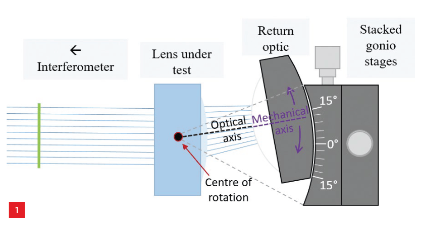
Typical goniometer stages have a fixed remote centre of rotation (RCR) distance, which is optimal for lenses with matching focal distance. In that case, the mechanical axis of the return optic can be aligned to the optical axis of the light beam (see Figure 1).
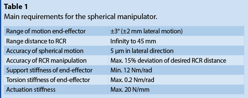
If the ‘lens under test’ is replaced by a lens with another focal length, the stacked gonio-stage is moved closer or further away from the interferometer to reflect the laser beam at the right distance. In that case, the RCR is no longer located at the lens centre, making it impossible to align the mechanical axis of the return optic to the optical axis. To accommodate a range of lenses with different focal lengths, a spherical manipulator is presented, of which the RCR can shift from 45 mm up to infinity (i.e. pure translation). Effectively, this spherical mechanism functions as a stacked gonio-stage with an adjustable RCR. Table 1 lists the main requirements.
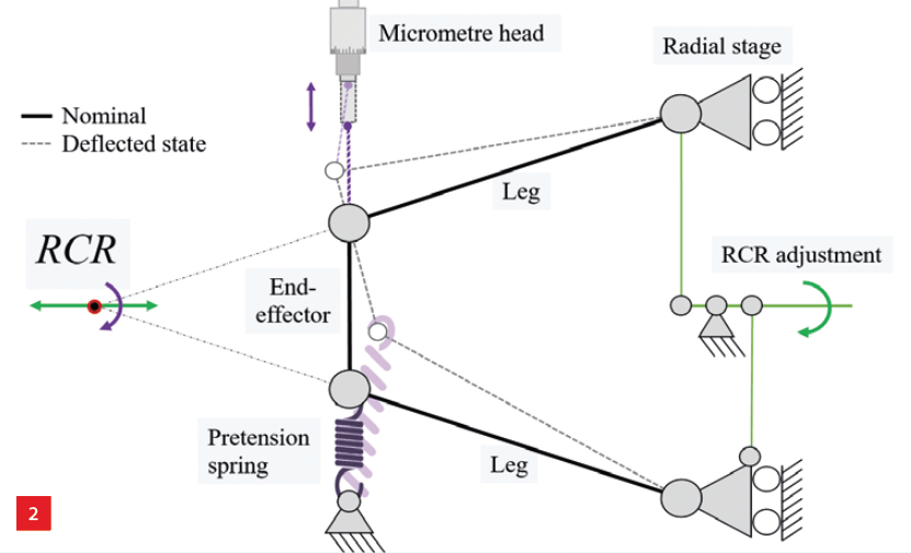
The proposed design (Figure 2) consists of three flexure-based legs that connect to the end-effector in a trapezoidal manner. The support lines of these three legs intersect in a common point, allowing for a spherical movement of the end-effector around this point. A radial displacement of the base connections of the legs results in the desired shift of the RCR along the centre-line of the mechanism.
design process.
After defining the kinematic, stiffness and accuracy requirements for the optical mount, various concepts were generated using a large overview with building blocks containing solutions to different aspects of the mechanism. Six different concepts were created by picking different combinations of building blocks. The first three concepts are based on a set of parallel legs that connect the end-effector to the base. The constraint lines associated with these legs are intersecting in the desired RCR.The other three concepts have an intermediate body.
In this article, concepts 1-3 are explained in more detail (see Figure 3).
These concepts use a trapezoidal mechanism with parallel links, which has several benefits compared to the other concepts (4-6). Higher support stiffness is achieved, because the axial stiffness of each link is added up. Mechanisms with a higher support stiffness produce a smaller error when a load is applied perpendicular to the actuated direction. Furthermore, all legs are manipulated in the same way when the RCR is adjusted, making these mechanisms less complicated.
All concepts were compared using criteria based on the requirements in a concept comparison table. The criteria with the largest weighted value were support stiffness and backlash. Concept 2 is superior in terms of support stiffness. However, the accuracy of the mechanism suffers from stick-slip in the pre-tensioned joints because of friction forces.
In concept 3, the folded leafsprings are twisted too much when manipulating the RCR, resulting in a collapse of the support stiffness. In the end, concept 1 was chosen for the flexure-based legs. Flexure-based spherical movements are less prone to back-lash, as flexures have no wearing parts, which makes the movements more accurate [2]. The flexures to move the legs outward in the rotating disk cannot achieve the required range of motion in the given design space. Therefore, the spiral ‘pin-in-slot’ mechanism of concept 2 is used.
![Figure 3. Three design concepts based on a set of parallel legs that connect the end-effector to the base. (a) Flexure-based trapezoidal mechanism. The legs (blue) are reinforced wire flexures, connecting the end-effector (green) to the base (grey). At the base, the legs move in radial direction using leafsprings. By rotating the purple disk, the RCR distance is adjusted. (b)Trapezoidal mechanism with conventional ball-socket joints. To eliminate backlash, the ball-socket joints are pre-tensioned by means of a spring (red). Deflection of the end-effector is uncoupled from the micrometers using leafsprings. A functional 3D-printed model of the mechanism is shown in the lower right. (c) Spherical motion is achieved using folded leafsprings as legs between the green and grey body. The fold lines of leafsprings intersect in the RCR. Tilting the angle of these lines shifts the RCR. Cartwheel hinges allow tilting of the folded leafsprings when the purple body contracts. The concept is based on the large-stroke spherical flexure joint (shown in the lower right figure), developed by the Precision Engineering group at the UT [1].](/.img/animated_true&w_2400&f_jpeg&q_100/dam/hightechsystems/public/showcases/spherical-mechanism-with-adjustable-centre-of-rotation/3a-Flexure-based-trapezoidal-mechanism_.jpg)
detailed design.
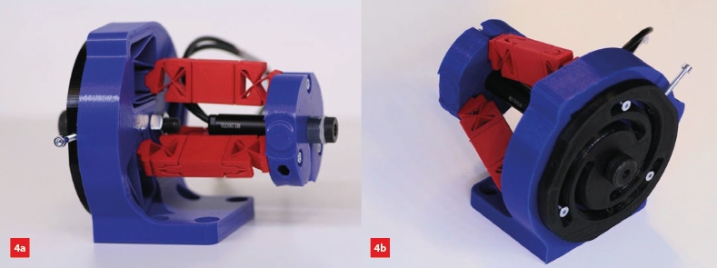
Figure 4 shows the functional model of the detailed concept. In the end-effector a laser pointer is mounted instead of a return optic. The laser was used for validation purposes. Newly developed flexure-based joints are integrated in each leg. These multi-degree-of-freedom flexure joints make use of a cartwheel hinge whose axis intersects perpendicularly with a short leafspring flexure. The legs therefore act as reinforced wire flexures that make up the edges of a spatial isosceles trapezoidal structure. Parallel flexure guides accommodate the radial movement of the base connection points for the RCR adjustment. A spiral guide synchronises the separation of the three legs. To demonstrate that the chosen concept can accomplish spherical motion, a pseudo-rigid-body model (PRBM) was used to illustrate how the orientation of the legs is changed when the distance towards the RCR is varied. In the PRBM, the flexures at the ends of the legs were replaced by ball joints. The kinematics were derived by means of this rigid-body model. By adding (rotational) spring elements to the joints of the PRBM, it was possible to derive the compliances of the system in the actuation and support [2].
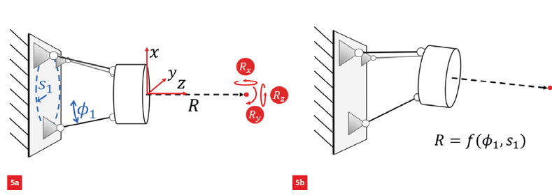
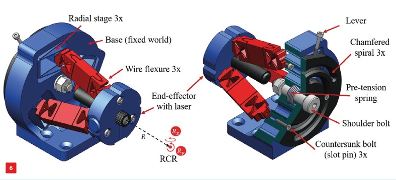
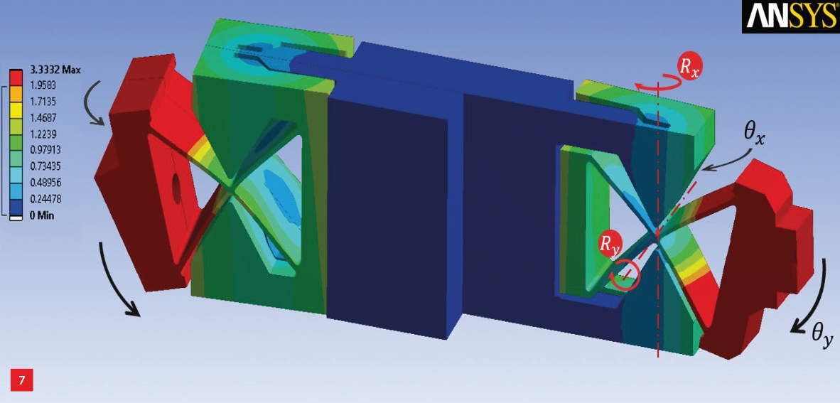
As implicitly shown in Figure 5 (and already explicitly illustrated for the 2D case in Figure 2), the RCR is located at the intersection of the three legs in the mechanism. In order to shift the RCR closer or further away from the end-effector, the joints at the base are radially shifted inward or outward. Varying radial distance (s1), ranging from 22 mm to 33 mm, to transform the mechanism from translating (R = ∞) to rotate about the RCR at the minimal distance from the end-effector (R = 45 mm), the legs have to tilt 22°, which requires a joint range of motion of ±11°. Together with the desired travel of the end-effector (±2 mm), the joints in the legs must be able to tilt ±15° in one direction (Ry ). Perpendicular to this tilting motion, the joints in the legs should be able to rotate ±2.5° in (Rx ) direction to allow for spherical movement as shown in Figure 6.
Three radial stages are present in the base to allow the radial movement of the legs, as shown in Figure 6. To prevent parasitic motion and save space, a compound parallel guide is used. By using two sets of antagonistic parallel leafsprings connected at an intermediate body, the parasitic motion of the first set is compensated by the second. In addition, space is saved by slightly angling the parallel leafsprings. These radial stages are actuated by a ‘pin-in-slot’ mechanism located at the backside of the base. The actuation of the radial motion of the wire flexure is accomplished by spiralling slots in a rotatable disk, which is attached at the back side of the base. This disk with slots rotates concentrically with the z-axis using a shoulder bolt. The ‘pins’ are attached to the radial stages and protrude through the spiralling slots. To eliminate backlash in these slots, countersunk screws are used in combination with chamfered edges of the spirals. In order to keep these slot pins and chamfered faces in contact, the disk is pre-tensioned by means of a spring over the shoulder bolt. An additional benefit of this pre-tensioning is that the mechanism is self-locking after adjustment of the RCR distance.
Large-range 3D-printed joint
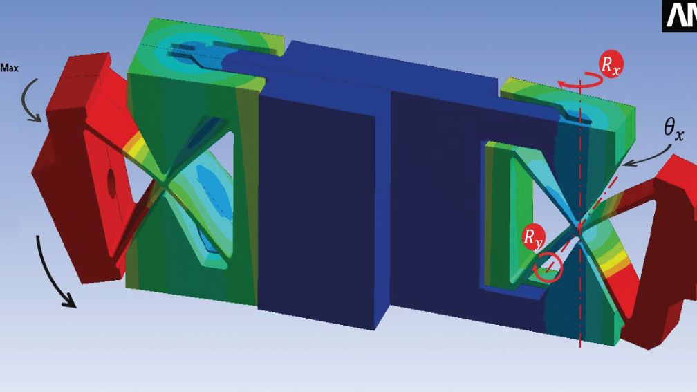
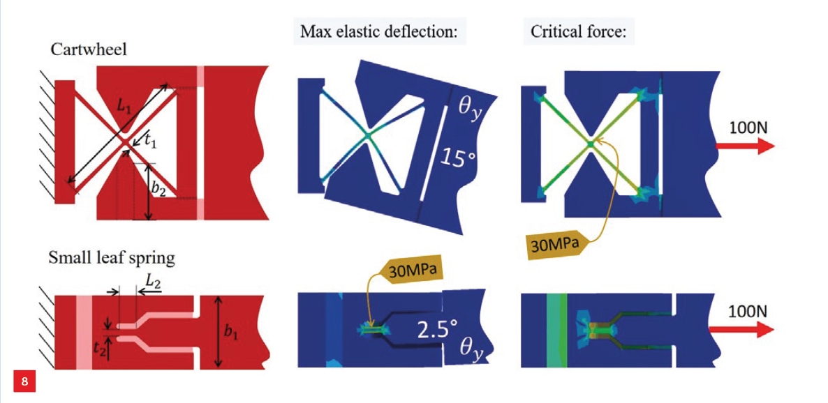
With the further detailing of a functional 3D-printed model of the mechanism, a new type of compliant cardan flexure has been developed. This compact joint provides a large range of motion in Ry (±15°) and a small range of motion (±2.5°) in the Rx-direction, while providing high axial stiffness in a compact space. The compliances in the legs are concentrated onto two cardan-based flexures with intersecting centres of rotation, as shown in Figure 6. Since the support stiffness benefits from a lumped instead of distributed compliance [3], a small leafspring hinge (SLSH) and cartwheel hinge (CH) are combined. The CH is responsible for the large deflection in Ry , while the SLSH can cope with the smaller rotation in Ry-direction. It is important that the rotation centres intersect, so that the location of the RCR of the spherical mechanism is the same for tip and tilting motions. The integration of the notch-type hinge into the support of the cartwheel hinge results in a compact cardan joint design. The designed cardan flexure is space-efficient, because the SLSH makes use of the unused space available at the sides of the CH flexure. In addition, the maximal allowable range of motion is physically limited by rigid parts of the joints in order to prevent the flexure from exceeding the yield stress.
To produce these flexures, 3D printing (fused deposition modelling, FDM) is the most suitable production method due to the presence of some undercuts. Other techniques, such as wire-EDM cutting, are feasible but require assembly from multiple parts. The geometry of the cardan joints in the legs was optimised using the mechanical properties of the PLA plastic that was used for the functional model. The range of motion was optimised for the highest axial stiffness.
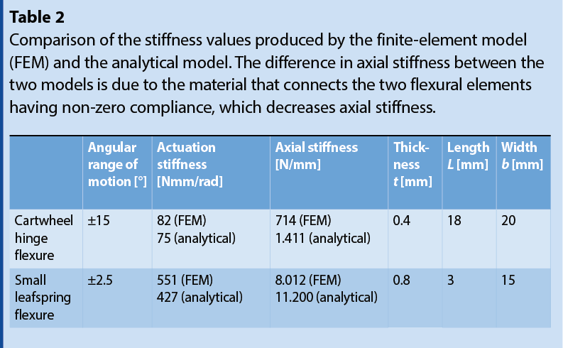
Two methods were used for analysing stiffness and range of motion. The first method relied on analytical approximations to predict the stiffness and maximal deflection of the joint using equations known from literature for the cartwheel and small leaf flexure joint [4]. These equations were used for calculating initial lengths. With a finite-element model (FEM) in ANSYS, a more detailed design of the joint as a whole was optimised (Figure 7). Figure 8 and the corresponding Table 2 present the optimised lengths and resulting design.
It was found that the printed legs were able to reach the desired range of motion without failing. However, for FDM printing it is important to keep the anisotropic behaviour of the resulting parts in mind. Layer adhesion limits the yield strength in the height direction to approx. 40% of that in virgin material. Therefore, the legs were printed with the side surface down, so stresses between layers are limited. Other influences on maximal yield strength of the material are print temperature, layer height, infill percentage, porosity and extrusion width [5], [6].
centre shift.
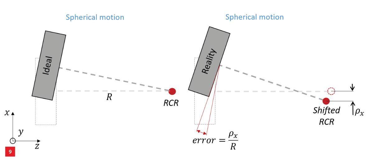
The mechanism was designed for spherical motion around a specified RCR. Ideally, the end-effector stays perfectly oriented towards this point for all motion. However, for this mechanism this is only the case in the initial position due to a kinematic change of the intersection point of the legs (Figure 2), also known as the shortening effect of the legs (see Figure 9). This causes more rotation of the end-effector for a given translation, resulting in a different RCR. This phenomenon is called ‘centre shift’.
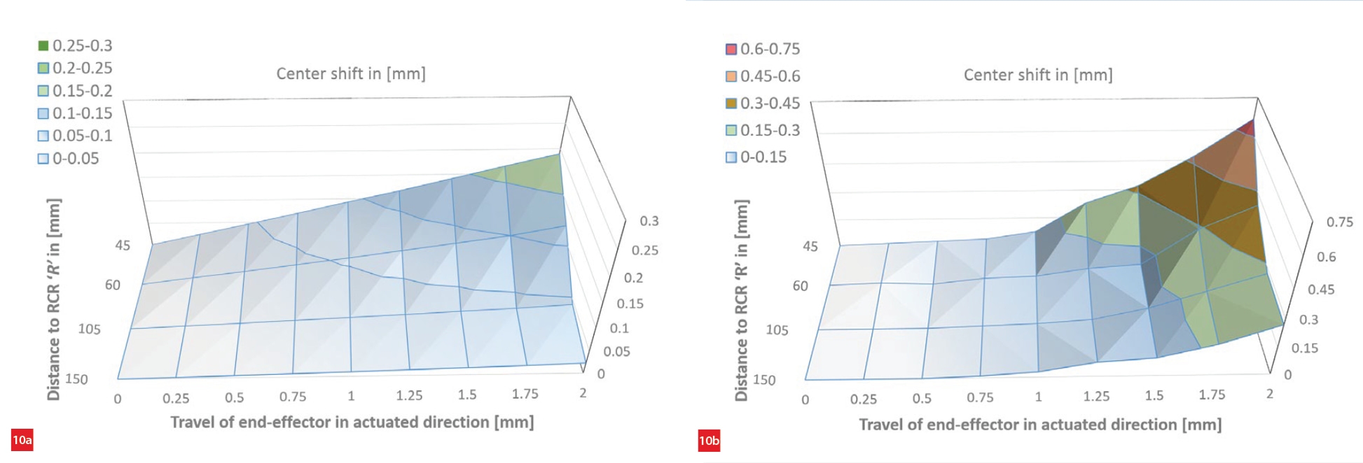
This centre shift was measured on the prototype by placing a camera sensor at the location of the desired RCR. The aforementioned laser pointer was mounted on the end-effector to illuminate the sensor at the RCR. In the ideal case, the camera sensor does not move during deflection. In practice, it does. Therefore, the change in spot location is taken as a measure for the centre shift. Figure 10 shows the centre shift computed by the kinematic model and measurements on the 3D-printed prototype.
As expected, the centre shift increases with larger deflections and shorter distance towards the RCR. From the experimental validation, it could be determined that the centre shift is much larger for deflections greater than 1.0 mm, up to 2.5 times larger than expected from the kinematic model. This is due to the finite support stiffness of the mechanism. Since the actuation force is applied at the end-effector and not in-line with the centre of compliance, an additional angular error is introduced, causing a ‘diving’ motion of end-effector.
conclusion.
An adaptive optical mount was developed. The resulting three-legged, flexure-based isosceles trapezoidal mechanism can perform the spherical motion about an adjustable remote centre of rotation, as needed for the alignment of lenses. Each leg consists of two new cardan joints that combine a cartwheel hinge and a short leafspring hinge for high support stiffness. For deflections larger than 1.0 mm at small RCR distances, the centre shift increases exponentially, whereas the centre shift in the kinematic model increases linearly. With the evaluation of the 3D-printed functional model it was found that the location where the actuators push or pull the end-effector is not optimal. To reduce the amount of centre shift this location is desired to be in the centre of compliance. This location is at the centre of the trapezoid to counteract axial forces in the legs when deflecting. Also, if this design would be realised in metal, the support stiffness would improve as well. Nevertheless, the design fulfills all requirements for the current application of lens testing.
references
[1] M. Naves, R. Aarts, and D. Brouwer, “Large-stroke spherical flexure joint”, Mikroniek, 59 (3), pp. 17-21, 2019.
[2] M. Wang, “Mechanical and geometric advantages in compliant mechanism optimization,” Frontiers of Mechanical Engineering in China, 4 (3), pp. 229-241, 2009.
[3] Howell, L.L., and Midha, A., “A Method for the Design of Compliant Mechanisms With Small-Length Flexural Pivots”, J. Mech. Des., 116 (1), pp. 280-290, 1994
[4] J. Wu, S. Cai, J. Cui, and J. Tan, “A generalized analytical compliance model for cartwheel flexure hinges”, Review of Scientific Instruments, 86, p. 105003, 2015.
[5] B. Wittbrodt, and J. Pearce, “The effects of PLA color on material properties of 3-D printed components”, Additive Manufacturing, 8, pp. 110-116, 2015.
[6] S. Rajpurohit, and H. Dave, “Analysis of tensile strength of a fused filament fabricated PLA part using an open-source 3D printer”, The International Journal of Advanced Manufacturing Technology, 101, pp. 1-4, 2019.