
introduction.
Nanometer-level precision in substrate positioning stages is a key requirement for advanced lithography systems. To enable ever-smaller chip features, the control bandwidth must be pushed to its limits. Demcon’s 6 Degree of Freedom (DoF) levitating stages must seamlessly interact with the dynamic behaviour of the overall system. To operate at the highest levels of precision, the control strategy ought to avoid exciting system resonances. At the same time, it must maintain a high bandwidth for effective disturbance rejection and fast settling times – often pushing the bandwidth close to these resonances.
Rigid-body decoupled control is commonly utilized, simplifying the design by treating the six DoFs as independent Single-Input Single-Output (SISO) control loops. Once decoupled, individual resonant frequencies can be efficiently attenuated using notch filters. This approach is typically preferred over full Multi-Input Multi-Output (MIMO) control due to its lower complexity, improved interpretability, and reduced implementation effort. However, this SISO approach becomes inadequate when dynamic crosstalk invalidates the decoupling assumption. As a result, both performance and stability predictions become unreliable.
This paper presents a pragmatic solution using Singular Value Decomposition (SVD) to guide notch filter design for systems with cross-coupled resonances. The method integrates seamlessly into the SISO framework, mitigating cross-coupling effects typically addressed by complex MIMO control — while preserving the simplicity of decoupled SISO controller design. By leveraging an enhanced SVD to identify dominant closed-loop directions associated with the largest singular values at resonant frequencies, notch filters can be applied selectively and efficiently. This approach minimizes phase loss near the control bandwidth and leverages SVD to guarantee stability. SVD thus enables a pragmatic, high-performance control solution for Demcon’s stages in demanding lithography environments.
setup.
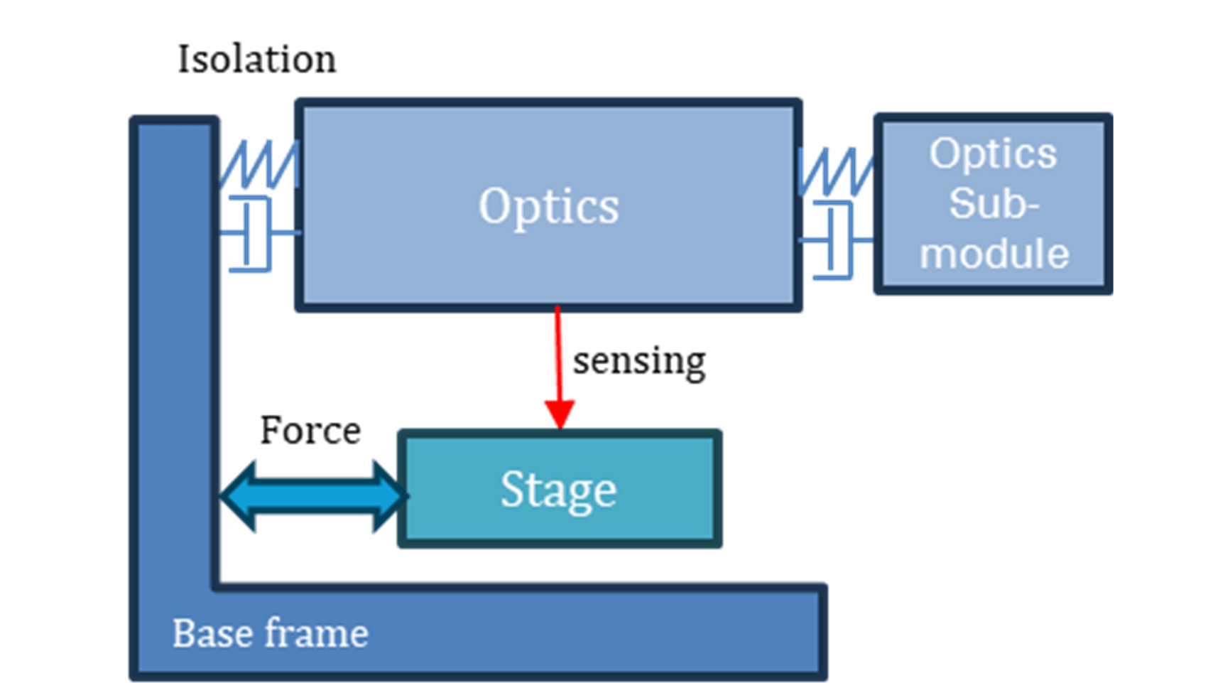
A typical lithography stage positions itself relative to an isolated optical system, as depicted in Figure 1. When the stage moves, it exerts reaction forces on the base frame, which also supports the optics. Despite isolation, some of these forces inevitably couple through, exciting the optics. This excitation perturbs the stage position relative to the optics.
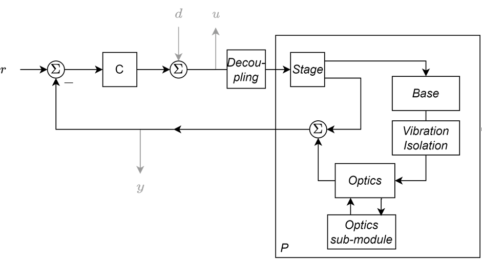
A feedback-loop, as shown in Figure 2, follows: control-induced stage accelerations lead to optical vibrations, which in turn affect the position measurements used by the controller. Additional submodules attached to the system further influence the dynamics. The combined system may introduce significant cross-coupling between DoFs, degrading performance, risking instability, and limiting achievable bandwidth – and thus positioning precision.
The crosstalk frequencies and resonant modes affecting performance are identified through data analysis, system identification, and modal analysis, and are treated as a given for the control design in this paper.
open-loop crosstalk directions.
Plant P(jω) is identified in closed loop using the signals u, d and y in all six DoF, as shown in Figure 2. From this, the 6x6 open-loop transfer function is constructed as:

For each frequency, the SVD of open loop L(jω) can be calculated [1] as:

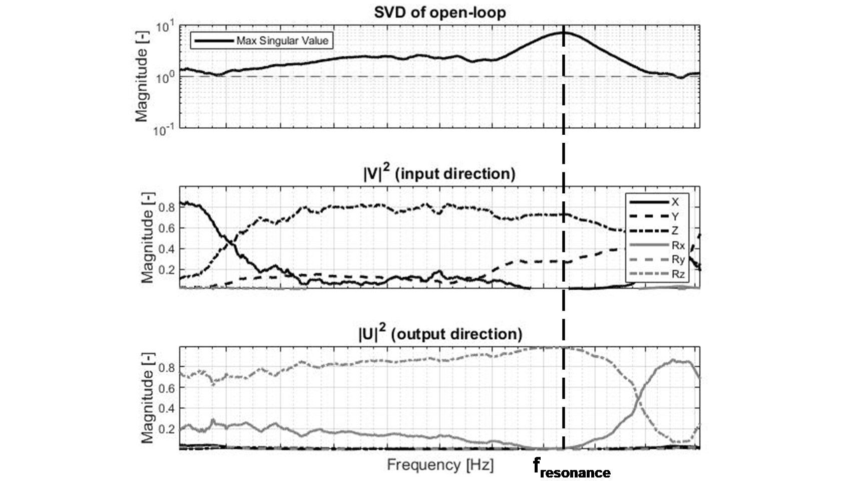
Here, Σ(jω) is a diagonal matrix containing singular values in descending order, U(jω) defines the output directions associated with these gains, and the complex conjugate of V(jω) represents the corresponding input directions. The largest singular value at each frequency, representing the dominant resonant mode, is given by the top-left entry in Σ and the corresponding entries in U and V.
SVD analysis therefore reveals the directions along which a resonance acts – information not accessible through standard SISO analysis. Figure 3 illustrates this with measured data: at fresonance, significant crosstalk occurs from Z and Y into Rz.
Key insight:
SVD visualization helps identification of dominant open-loop resonance directions.
stability.
SISO stability margins – Phase Margin (PM), Gain Margin (GM) and Modulus Margin (MM) – are applied in the frequency range where the system can be considered decoupled, i.e., up to some coupling frequency fcoupling. Within this range, the decoupling assumption holds, allowing conventional SISO tools to be used reliably. Beyond fcoupling, cross-coupling effects become significant, invalidating SISO-based stability metrics.
For frequencies beyond fcoupling, stability is assessed using the small-gain theorem. This split approach – using SISO analysis below fcoupling and the small-gain theorem above – requires the system to be linear, as only linear systems do not introduce additional frequency components. If stability can be demonstrated across all frequencies – using SISO margins in the decoupled regime and the small-gain theorem in the coupled regime – then overall closed-loop stability is guaranteed.
Let H(jω) represent a closed loop that is opened at some arbitrary point. The small-gain theorem for a linear multivariable system at frequency ω states that system H(jω) is stable if [1]:
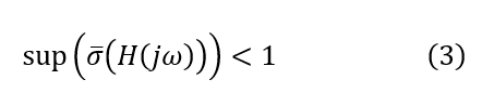
where σ⋅ denotes the maximum singular value of Hjω i.e., the left-top element of Σjω in the decomposition of Hjω. This condition is used to design notch filters at the crosstalk frequencies along the identified directions.where σ⋅ denotes the maximum singular value of Hjω i.e., the left-top element of Σjω in the decomposition of Hjω. This condition is used to design notch filters at the crosstalk frequencies along the identified directions.
Stability criterion:
If the frequency corresponding to the gain margin, fGM, satisfies fGM≪fcoupling for all DoFs, then overall stability is ensured provided that:
- SISO stability margins (PM, GM, MM) are satisfied for all DoF, and
- the small-gain criterion, Equation 3, holds for all f≥fcoupling.
closed-loop crosstalk directions.
So far, SVD has been used to identify open-loop resonance directions. However, stages operate in closed-loop control, where the interaction between DoFs is influenced by feedback. To capture this, SVD analysis must be enhanced to reflect closed-loop dynamics.
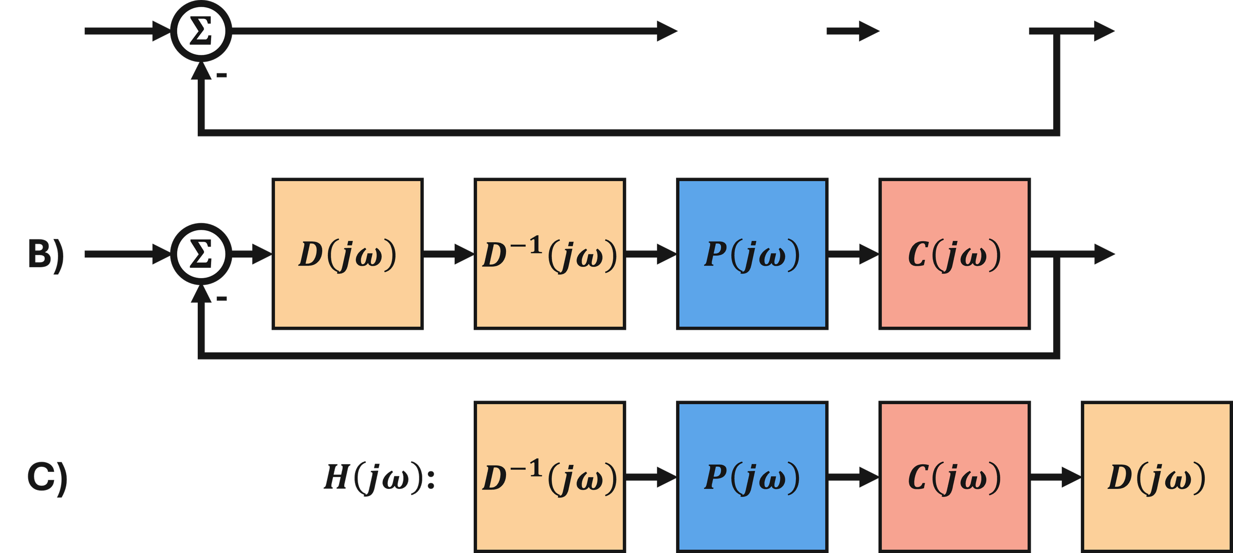
This is achieved using D-scaling, a technique found in μ-synthesis (as part of the D-K iteration in H∞ control) [1]. While D-scaling is often introduced as a mathematical tool, it also provides physical insight into how feedback alters resonance directions in closed-loop systems. This is illustrated by the 2D example following this section. Figure 4 shows the concept: Loop A) (Equation 1) is augmented with an invertible matrix Djω and its inverse, resulting in loop B) (Equation 4).

Loops A) and B) are dynamically equivalent. To apply the small-gain theorem, which allows the loop to be opened at any arbitrary point, the loop is opened between D(jω) and D-1(jω), giving C) (Equation 5):

If stability is proven for H(jω) using the small-gain theorem, then the original loop as in Equation 1 is also stable, since Equation 4 is dynamically equivalent. Matrix D(jω) is chosen to minimize the largest singular value of H(jω):

Minimizing σ, which is used to assess stability, reduces conservatism. For simplicity, D(jω) is chosen to be a strictly positive real diagonal matrix. One value can be fixed to unity without loss of generality [1], giving a total of 5 optimization variables. This optimization, proven to be convex [1], is solved per frequency point.
The SVD of H(jω) with D-scaling better reflects closed-loop resonance directions, because the scaling introduced by D(jω) can account for the relative loop gains in feedback.
2D example: closed-loop crosstalk directions.
A 2D example follows to illustrate this concept.
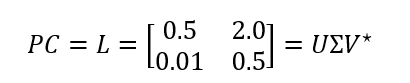
Consider a 2D system, L, evaluated at a single frequency.
The singular value decomposition (SVD) yields:
The input direction VL indicates that the resonance is primarily driven by the second state, while the output direction UL shows that the resonance manifests mainly in the first state. The largest singular value (2.12>1) suggests potential instability in the system. However, physical intuition suggests that the closed loop is stable, since both states are stable in themselves (gain of 0.5), and the strong coupling from state 2 to 1 (gain 2.0) is not reciprocated (gain 0.01 from 1 to 2).
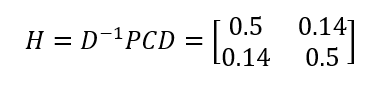
This is where D-scaling becomes essential: it modifies the analysis to reflect the closed-loop behavior rather than just the open-loop directions. Utilize the following diagonal real D-matrix:
D = diag ([1,0.07 ])
The augmented open-loop system becomes:
The SVD of H is:
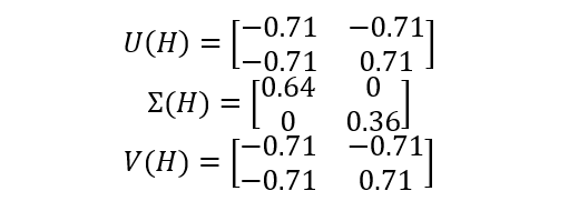
Key insights:
- Without D-scaling, SVD analysis reflects open-loop interactions, which may be overly conservative.
- With D-scaling, closed-loop behavior is assessed, avoiding unnecessary notches.
notch design.
An optimization algorithm is employed to tune notch filter settings until the stability criteria as outlined above are robustly satisfied, significantly reducing manual design effort. The algorithm minimizes the phase loss introduced by the notches at the controller bandwidth, enabling the highest feasible bandwidth for optimal disturbance rejection and rapid settling.
results.
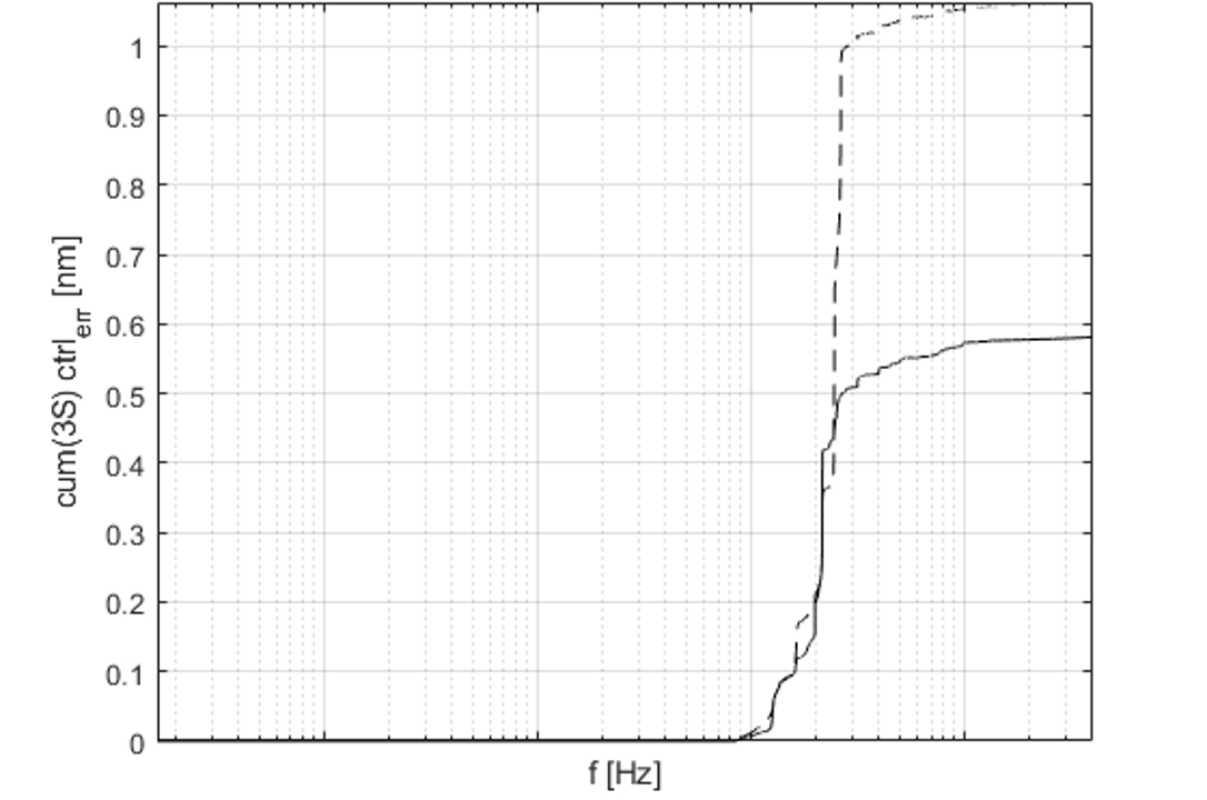
The proposed methodology is applied to a high-performance levitating stage with nanometer – level precision. Figure 5 compares two cases: (1) tuning based solely on SISO stability metrics (with notch tuning algorithm applied for bandwidth optimization) and (2) the approach as outlined in this paper, incorporating SVD-based notch placement. Including cross-coupling modes in the notch design nearly halves the cumulative control error, significantly improving stage performance.
conclusion.
This paper presented a pragmatic method for high-precision control of 6-DoF lithography stages subject to significant crosstalk. By extending SVD analysis with D-scaling to capture closed-loop resonance directions, the approach enables target notch filter design that mitigates cross-coupling resonances without resorting to full MIMO control – thus preserving the simplicity of decoupled SISO control design. An optimization-based notch tuning strategy further minimizes phase loss, enabling Demcon’s levitating stages to achieve maximum bandwidth for optimal disturbance rejection and settling performance. Experimental results demonstrate that including cross-coupling modes in the notch design can nearly halve the cumulative control error, highlighting the effectiveness and industrial relevance of the method.
References
- Skogestad S, Postlethwaite I. Multivariable Feedback Control: Analysis and Design. 2nd ed. Chichester: John Wiley & Sons; 2005. ISBN: 978-0-470-01168-3.