
Key advantages
This approach poses several advantages over conventional Tuned Mass Dampers:
- Adds virtually no mass or volume
- Remains tunable
- Integrates easily within flexure mechanisms
Moreover, this active approach allows suppression of a particular frequency without deteriorating others, which is difficult to achieve with viscous or viscoelastic dampers.
The demonstrator setup shows the technique on a 6 degree-of-freedom (DoF) system. Piezoelectric patches are used to suppress the nominal eigenfrequency of a newly designed six-DoF flexure-based vibration isolation system.
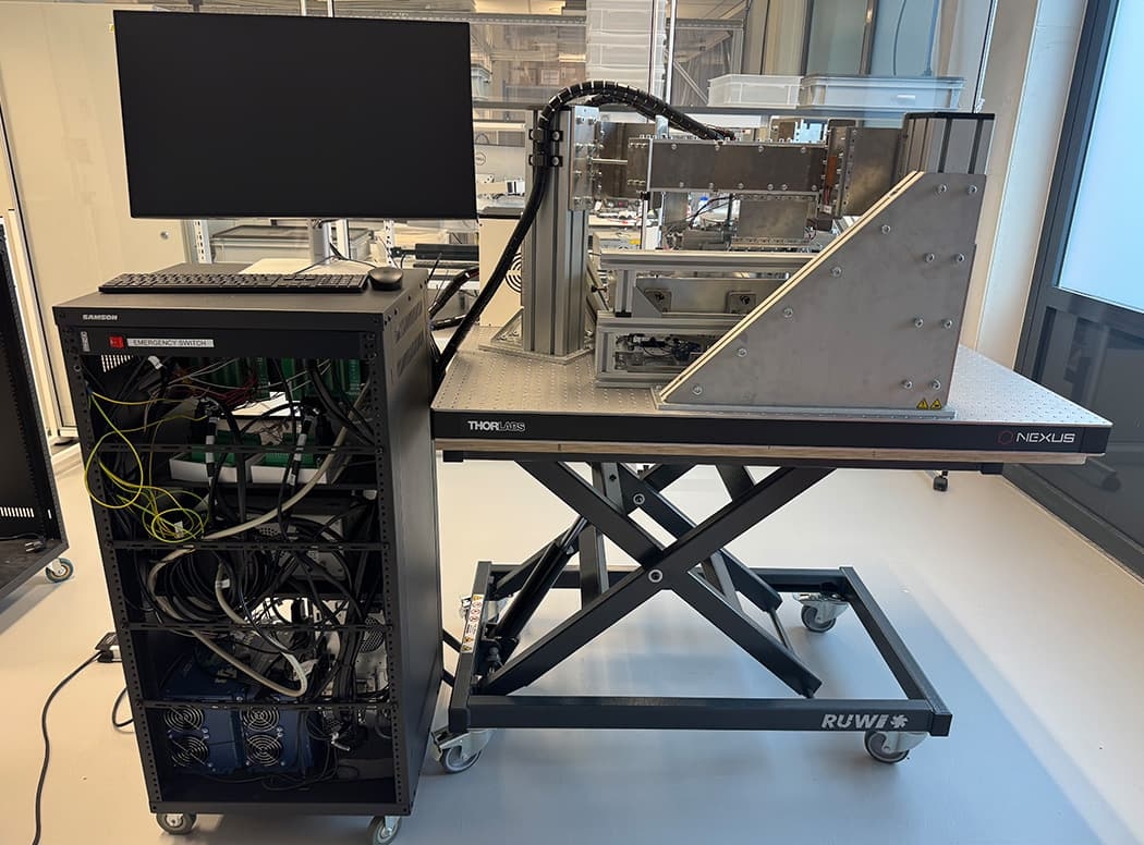
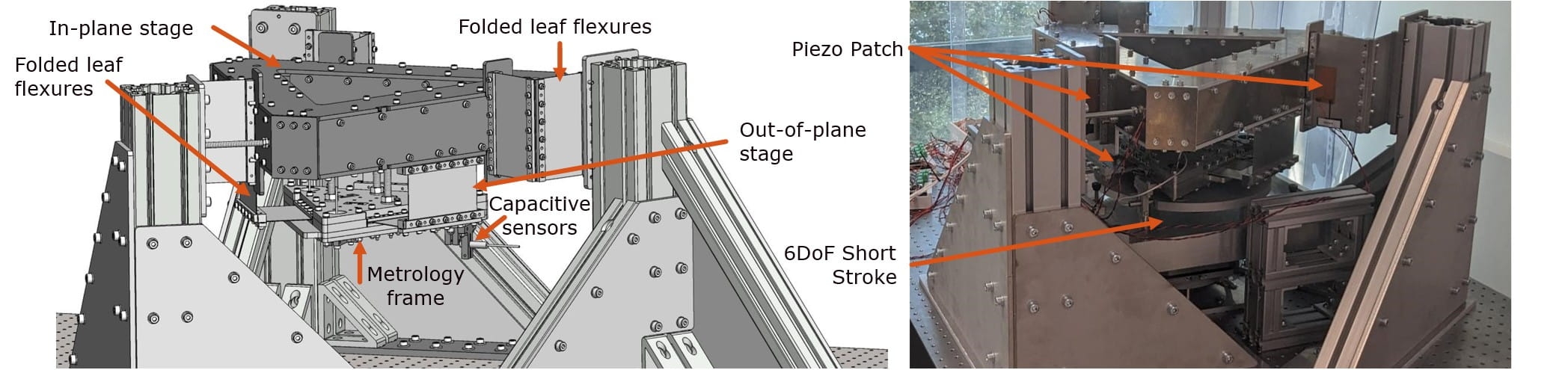
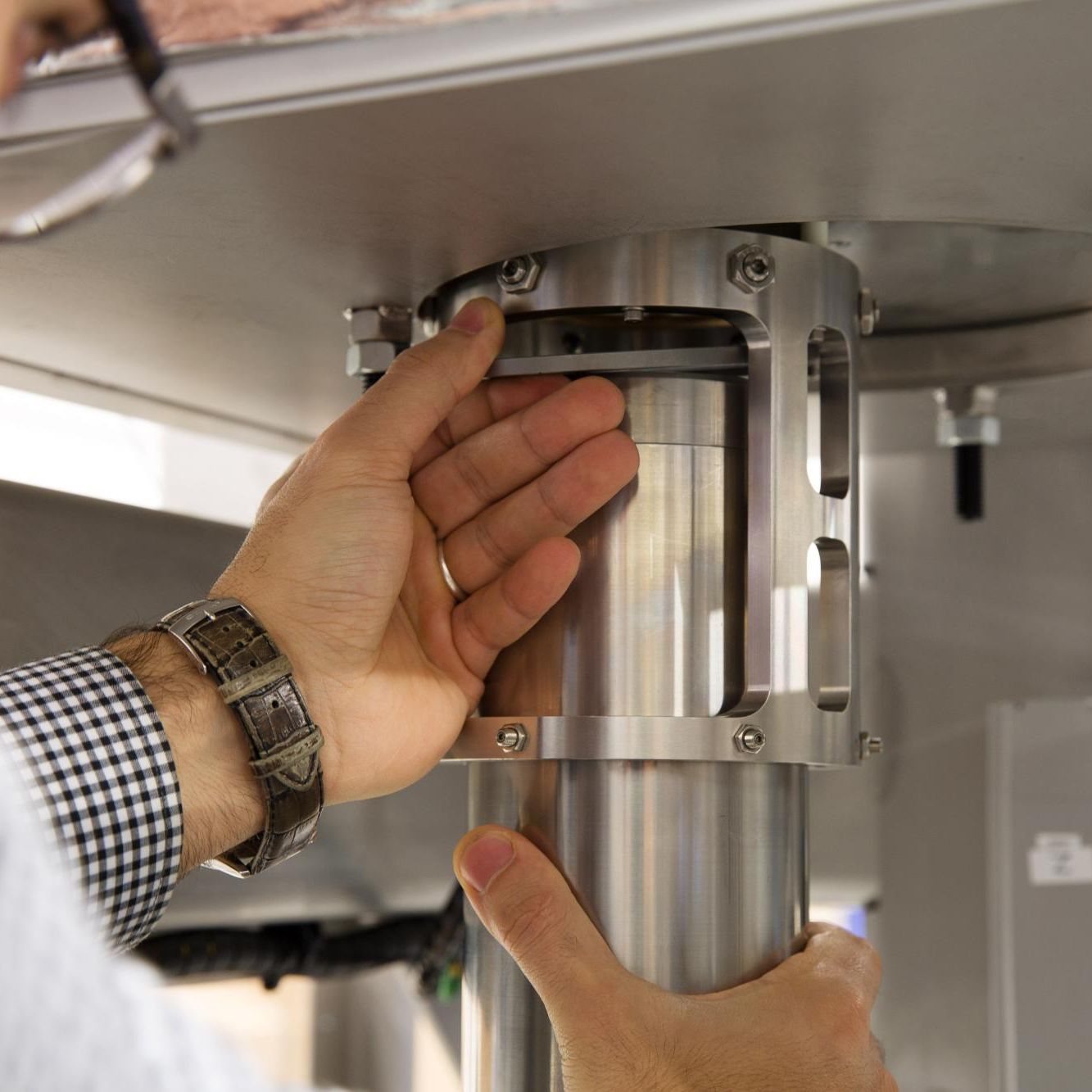
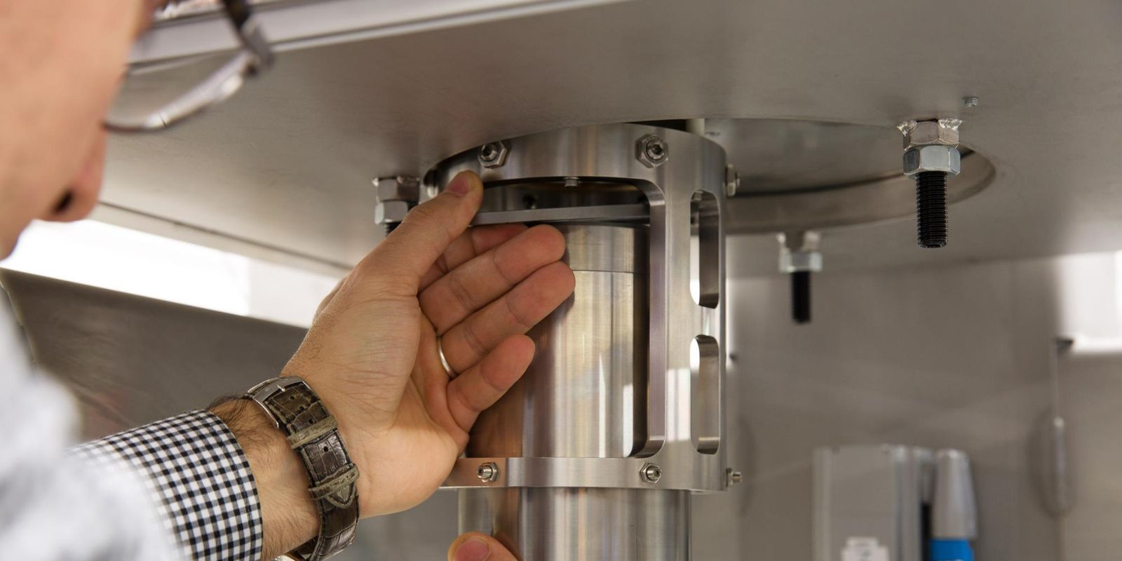
Figure 1 shows the designed system, consisting of two stages with three folded leaf flexures each. The first stage releases in-plane modes, while the second stage releases out-of-plane modes, together freeing all six DoF with a suspension frequency between 10 and 22 Hz. The six-folded leaf flexures have an integrated piezoelectric sensor and actuator in the form of a bimorph flexure, see Figure 2.
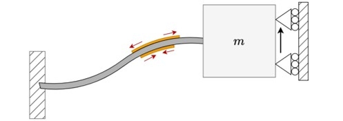
Figure 2 shows a schematic of a piezoelectric bimorph. Applying a voltage over the lower patch causes it to contract, bending the leaf flexure and moving mass m upwards. This stretches the top patch, resulting in an output voltage, allowing it to be used as a sensor detecting the movement.
design approach.
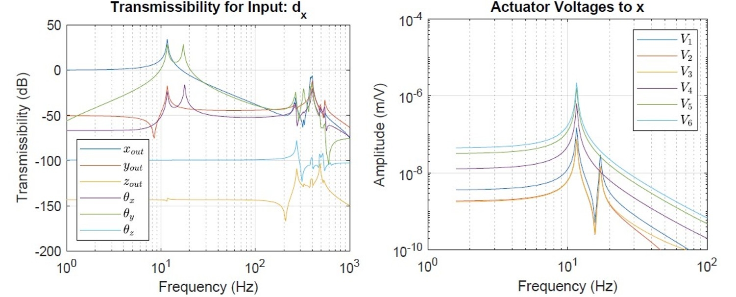
Key to the design's success was the utilization of the piezoelectric extension to the multibody software SPACAR [3], allowing for rapid design iterations and concept selection. Example results are shown in Figure 3. SPACAR was employed for two main purposes. First, it analyzed the vibration transmissibility from the floor to the metrology frame, indicating the nominal suspension modes and parasitic resonances. Second, it indicated the coupling from piezoelectric patch voltage to metrology frame movements, ensuring that the patches were able to suppress the nominal modes.
Transmissibility results were validated using conventional Finite Element Analysis. After building, system identification and structured parameter estimation helped in determining the actual mode shapes. This identification largely aligned with the SPACAR predictions, as shown in Table 1.
Table 1. Resonance mode frequencies as predicted by SPACAR, validated through Finite Element Analysis (FEA), and measured on the setup. These six modes are nominal suspension modes; higher modes are parasitic.
|
Frequencies [Hz] |
Mode 1 |
Mode 2 |
Mode 3 |
Mode 4 |
Mode 5 |
Mode 6 |
|
SPACAR |
11.6 |
11.6 |
13.1 |
14.3 |
18.5 |
19.1 |
|
FEA |
10.3 |
10.3 |
12.2 |
13.3 |
18.9 |
18.9 |
|
Measured |
12.3 |
12.5 |
14.2 |
15.2 |
20.4 |
21.0 |
Modal decoupling was used to achieve a sufficiently decoupled system up to 25 Hz, indicated by the Relative Gain Array (RGA) being below 0.1 for those frequencies. This permitted a decoupled control approach for the six nominal suspension frequencies. A Positive Position Feedback (PPF) controller was tuned for each nominal mode, using H2-optimal tuning.
Figure 4. This mode is defined by -396x -478y. The input spectrum consists of white noise generated by the Short Stroke actuators, with the Short Stroke clamped in position. The parasitic modes observed between 60 and 197 Hz are caused by the clamping of the Short Stroke, making them results of the measurement method rather than internal modes [2].
![Left: Normalized measured impulse responses for Modeshape 1, scaling the maximum amplitude to 1. Right: Normalized measured Power-Spectral-Density (PSD) in [1/Hz] for Modeshape 1.](/.img/animated_true&w_2400&f_jpeg&q_100/dam/hightechsystems/public/showcases/Piezoelectric-damping-of-a-6-DoF-vibration-isolation-frame/Left-Normalized-measured-impulse-responses.-Right-Normalized-measured-Power-Spectral-Density.jpg)
results & conclusion.
The approach significantly increased modal damping from 0.4%-1.1% to 9%-13% [2]. Figure 4 shows the time and frequency domain improvements for one of the six mode shapes, with piezoelectric control damping the 13Hz resonance mode.
In conclusion, this work supports and highlights the potential of implementing piezoelectric damping within industrial applications. It is demonstrated that, with the current tools available, integration of piezoelectric patches can yield a substantial increase in modal damping, with values up to 13% being achieved. The comprehensive approach, from system design to experimental validation, provides a robust framework for future industrial applications.
solve challenges for and with you
We believe in the power of partnerships. So, to deliver as promised, we combine expertise, experience, and domain knowledge to create a winning team. Working side-by-side, creating shared value.
more cases & tech insights.
Cracking the glass code
We have grown accustomed to metal and concrete printing. But glass? It not only has a very high melting point, it also becomes brittle after solidifying too quickly. Together with the German specialist in advanced solutions from high-performance materials QSIL we cracked the ‘glass code’.
Read more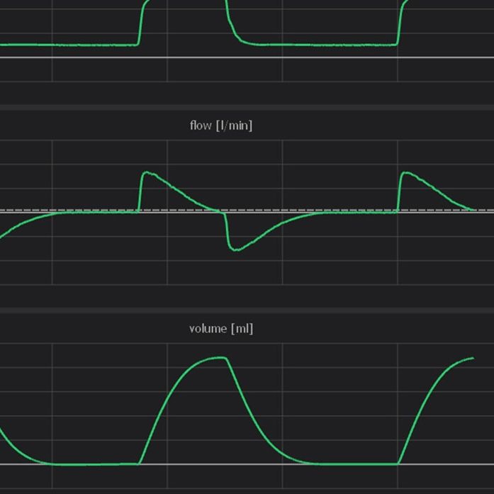
Use cases in machine learning for time series
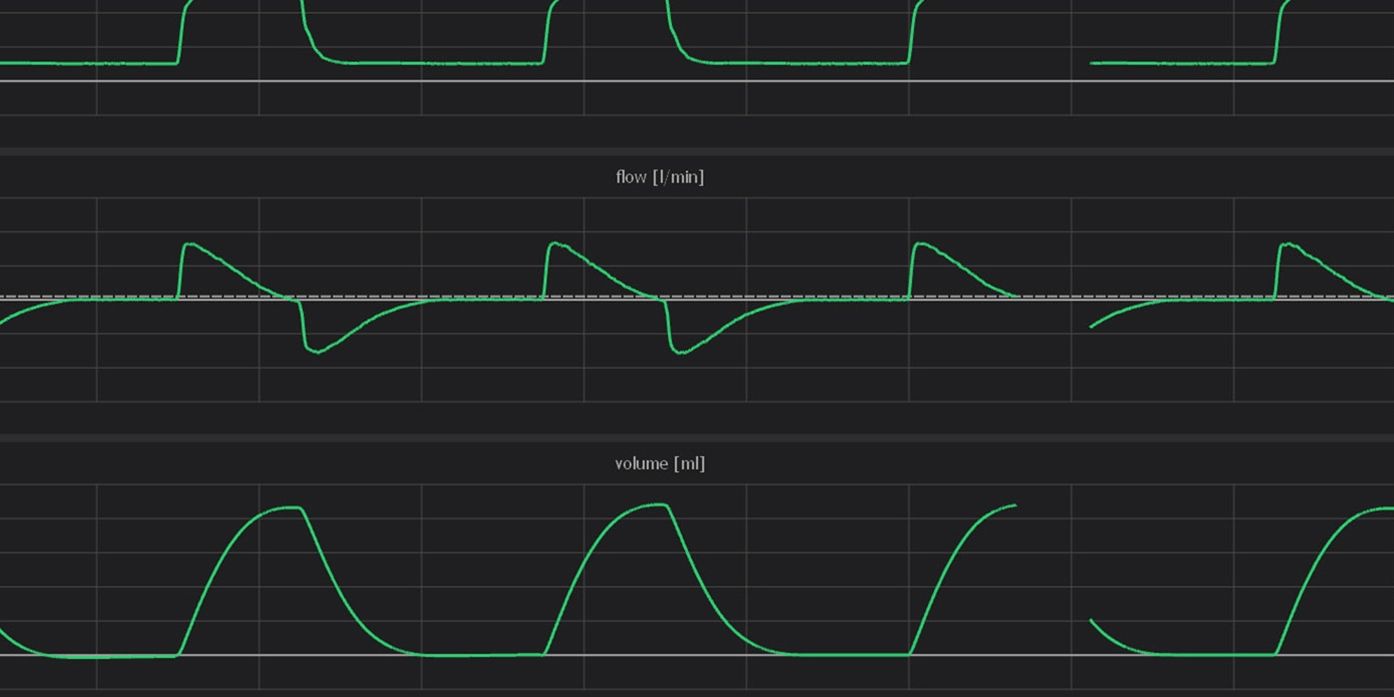
It is essential that the ventilator support is synchronized (in time) with the patient’s spontaneous breaths. A mismatch in this timing is referred to as Patient-Ventilator Asynchrony (PVA). To improve the patient’s comfort and recovery this PVA must be prevented. A key step in this process is the detection and classification of PVA.
Read moreDSPE knowledge day engineering for cryogenics.
Despite storm Ciarán, nearly 40 professionals gathered at ASTRON during the DSPE Knowledge Day to explore challenges and innovations in cryogenic engineering.
Read more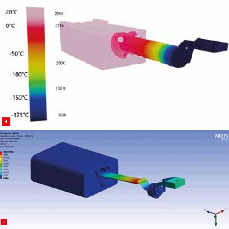
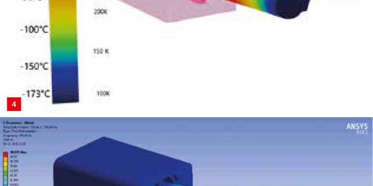
Cryoem zero-vibration cold tip
Demcon kryoz designed an efficient cryogenic micro-cooler that has a low form factor and demonstrated its high mechanical and thermal stability.
Read more